Your Basket Basket

(0 items £0.00)

Checkout
For sales & advice - Mon - Fri, 9.30am - 4.30pm
 0330 174 08510330 174 0851
Or email us here

Lock Shop Direct measurement guide

How to Measure and Choose Gate Security

Use this guide to record the dimensions and operating requirements for locks, latches, digital locks, drop bolts and other security hardware on timber and metal gates.

Important: Measure the gate, post and closed gap at the intended lock height. Also consider handing, access from both sides, weather exposure, gate movement and any safety requirement.

1. Identify the gate and operating arrangement

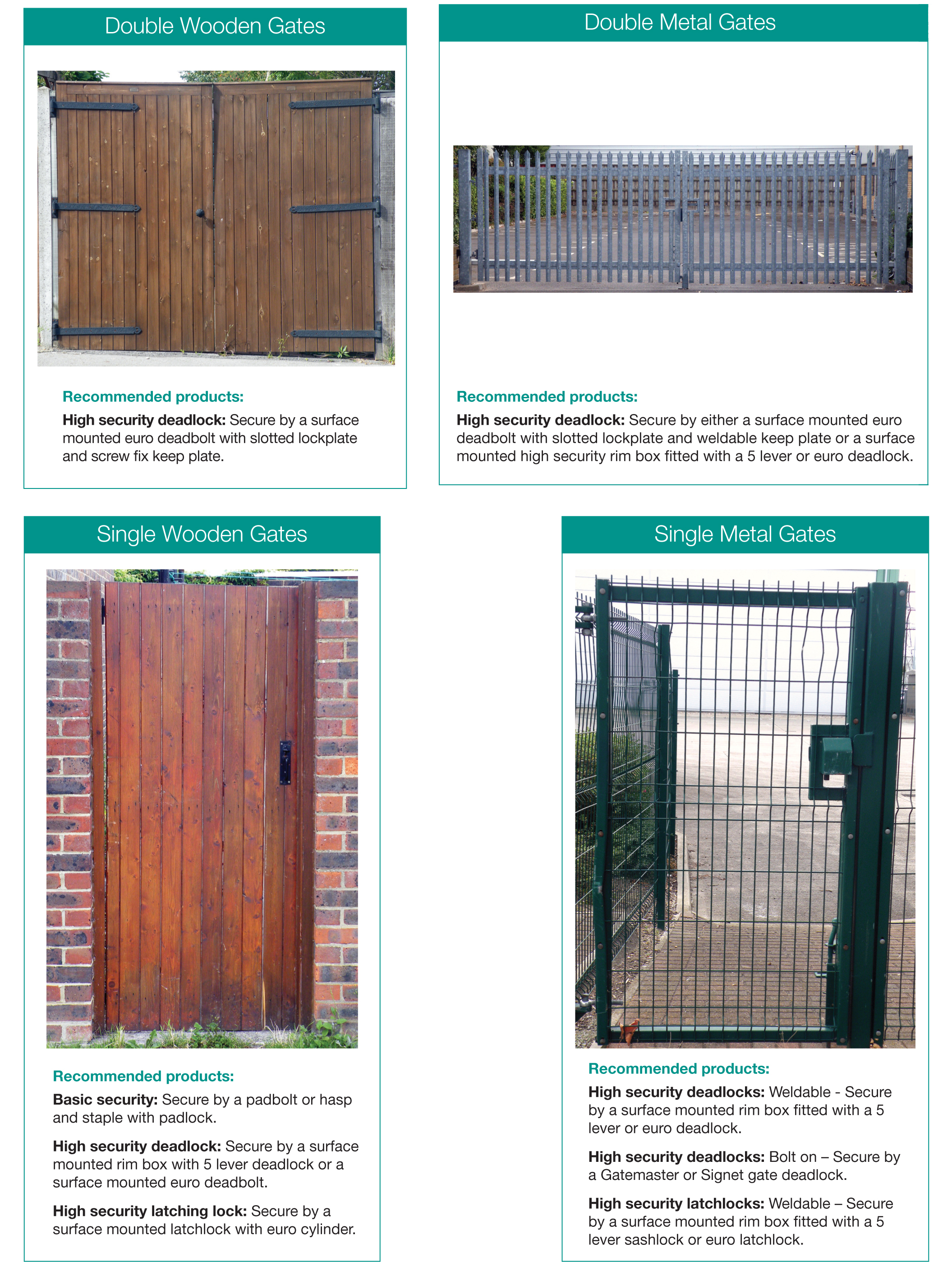
Start by recording the gate construction and how it moves. A lock for a timber pedestrian gate is selected differently from hardware for a steel driveway or sliding gate.

Timber pedestrian gate

Record stile width, gate thickness, post size and gap. Surface-mounted locks may be simplest.

Metal framed gate

Measure the box-section or flat-bar profile and available welding or bolt-on surface.

Double driveway gate

Identify active and passive leaves, centre gap, drop bolts and ground stops.

Sliding gate

Record gate/frame profile, travel direction and where the lock meets the post or receiver.

Grille or mesh gate

Check reach-through risk and whether protective shrouds or double-sided control are needed.

Powered gate

Locking, controls and safety devices form one machine system and require competent assessment.

2. Take the essential gate measurements

Measure at the intended lock height because gates and posts may taper or be out of square.

What to check How to measure or identify it Record
Gate thickness/profile Thickness of timber or dimensions of metal box section. _____ mm
Lock stile width Available flat width on the closing edge for the lock body. _____ mm
Post/receiver width Available fixing area for the keep or strike. _____ mm
Gate-to-post gap Clear gap when the gate is correctly closed. _____ mm
Backset For mortice or digital locks, edge to spindle/keypad centre line. _____ mm
Centres Spindle to cylinder, keyhole or turn centre where applicable. _____ mm
Opening direction Inward/outward or sliding, plus hinge side when viewed from a stated side. ________

3. Match the lock and keep arrangement

Surface gate lock

Record case size, fixing surface, latch projection and keep offset.

Mortice gate lock

Check the frame has sufficient depth and wall thickness for the case and fixings.

Weld-on lock

Measure the metal profile and confirm material, welding position and corrosion protection.

Digital gate lock

Check gate thickness, backset, spindle, code access, handing and weather rating.

Magnetic or electric lock

Record power, controls, cable route, alignment and required fail-safe/fail-secure operation.

Drop bolts and gate stops

Measure ground clearance, bolt throw, receiver position and the active/passive leaf sequence.

Allow for gate movement, sag and thermal expansion. The keep should guide the latch without forcing the gate out of alignment.

4. Decide how the gate must operate

  • Key, lever, knob, thumbturn, code, card, fob or remote operation.
  • Access required from one side or both sides.
  • Keyed alike or master-keyed with other doors or padlocks.
  • Free egress or controlled exit from the secure side.
  • Self-latching, hold-open or automatic-closing requirement.
  • Protection against reaching through the gate to operate the inside control.
  • Weather, coastal exposure and suitable corrosion-resistant finish.

If the gate forms part of an escape route, boundary to a pool, school or other controlled area, check the relevant safety and access requirements before choosing the operation.

5. Powered gates and safety systems

Powered-gate warning: Do not add, remove or reposition locks on a powered gate without considering the complete gate machine, controls and safety devices. Powered gates require site-specific risk assessment and competent installation and maintenance.
  • Do not create new trapping, crushing or shearing points.
  • Do not bypass safety edges, photocells, force limitation or emergency release.
  • Confirm how the lock interfaces with the operator and control panel.
  • Isolate power before inspection where required and leave the gate in a safe condition.
  • Use the original gate manufacturer or a competent gate specialist for substantial changes.

Still not sure which product you need?

Send our team clear photographs and your measurements before ordering. Please include:

  • A full photograph of the gate, posts and hinges from both sides.
  • Gate material, thickness or metal profile dimensions.
  • Lock stile, post and closed-gap measurements.
  • Opening direction, active leaf and required access method.
  • Whether the gate is powered, self-closing or part of an escape route.

Sales and technical advice
Monday to Friday, 9:30am to 4:30pm

Telephone:
0330 174 0851

Email:
info@lockshopdirect.co.uk

Browse gate securityAll measurement guides

This guide is intended to help identify and measure replacement hardware. Product designs, terminology and handing conventions can vary by manufacturer. Always compare the complete product specification and fitting instructions. Where a door or fitting forms part of a fire escape, fire door, powered system or other safety-critical installation, obtain advice from a competent person before ordering or altering the hardware.


Your session will expire in xx.xx. Do you wish to Continue or Log Out
Your session will expire in xx.xx
Continue or Log Out